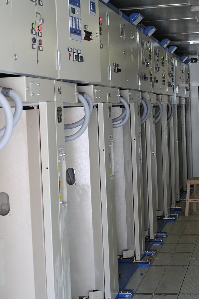
The structure of the switchgear due to the main circuits diagram can include:
- Single-pole circuit-breaker cubicle of the feeding line of the electric traction network or standby circuit-breaker (correspondingly for the connection of the feeding line of the electric traction network with the collecting buses of the switchgear or the main collecting bus of the switchgear with the standby one);
- Single-pole circuit-breaker cubicle for ice melting (for connection of the power supply line with voltage of 110 kV and more with the collecting buses of the switchgear);
- Two single-phase voltage transformers cabinet, their fuses and surge arrester;
- Double-pole input circuit-breaker cubicle (for connection of the winding of the corresponding voltage of the power transformer with the collecting buses of the switchgear);
- Cabinet of double-pole circuit-breaker of two-wire-rail power supply line (for connection of two-wire-rail power supply line with the collecting buses of the switchgear);
- Single-pole circuit-breaker cubicle of filtering and compensation device (for connection of the compensatory and reactor installation of the filtering and compensation device with the double-pole circuit-breaker cubicle of the filtering and compensation device);
- Double-pole (double-chamber) circuit-breaker cubicle for connection of the filtering and compensation device with the collecting buses;
- Cabinet of double-pole sectional jumper wires (for connection of the bus sections of the switchgear between each other).


